Programming SPI flash memory is a vital skill for anyone working with electronics, whether you’re updating firmware, repairing devices, or building embedded systems. The RT809H universal programmer is a powerful and flexible tool that simplifies this process, supporting both in-socket and In-System Programming (ISP) for SPI flash chips. we’ll walk you through everything you need to know to program SPI flash with RT809H, from setup to troubleshooting, in a clear and actionable way.
What is SPI Flash?
SPI flash is a type of non-volatile memory that uses the Serial Peripheral Interface (SPI) protocol to communicate with devices. It retains data even without power, making it ideal for storing firmware, configuration settings, or boot code in embedded systems like microcontrollers, routers, and IoT devices. Common SPI flash chips, such as the Winbond W25Q64FV, come in packages like SOIC8 or WSON and vary in capacity from a few kilobytes to hundreds of megabits.
Unlike other memory types like NAND or NOR flash, SPI flash is known for its simplicity, speed, and small size, which suits it for applications requiring quick read/write access. Understanding its role helps you appreciate why tools like the use RT809H are so useful for programming it.
Overview of the RT809H Programmer
The RT809H is a universal programmer designed to handle a wide range of memory chips, including SPI flash (24/25/93/95 series), NAND flash, and eMMC. Its standout features include:
- High-Speed USB 2.0: Transfers data at up to 25 MB/s for fast programming.
- Automatic Chip Detection: Identifies chip models to streamline setup.
- Dual Programming Modes: Supports in-socket programming via a Zero Insertion Force (ZIF) socket and ISP for chips soldered onto boards.
- Wide Compatibility: Works with Windows XP, Vista, 7, 8, and 10.
The RT809H comes with adapters like SOIC8, SOP16, and TSOP48, making it versatile for different chip packages. Whether you’re working on a standalone chip or a device in a live circuit, this tool has you covered.
Programming SPI Flash In-Socket
In-socket programming involves removing the SPI Flash with RT809H chip from its circuit and placing it into the RT809H’s ZIF socket. Here’s a step-by-step guide:
Step 1: Install the Software
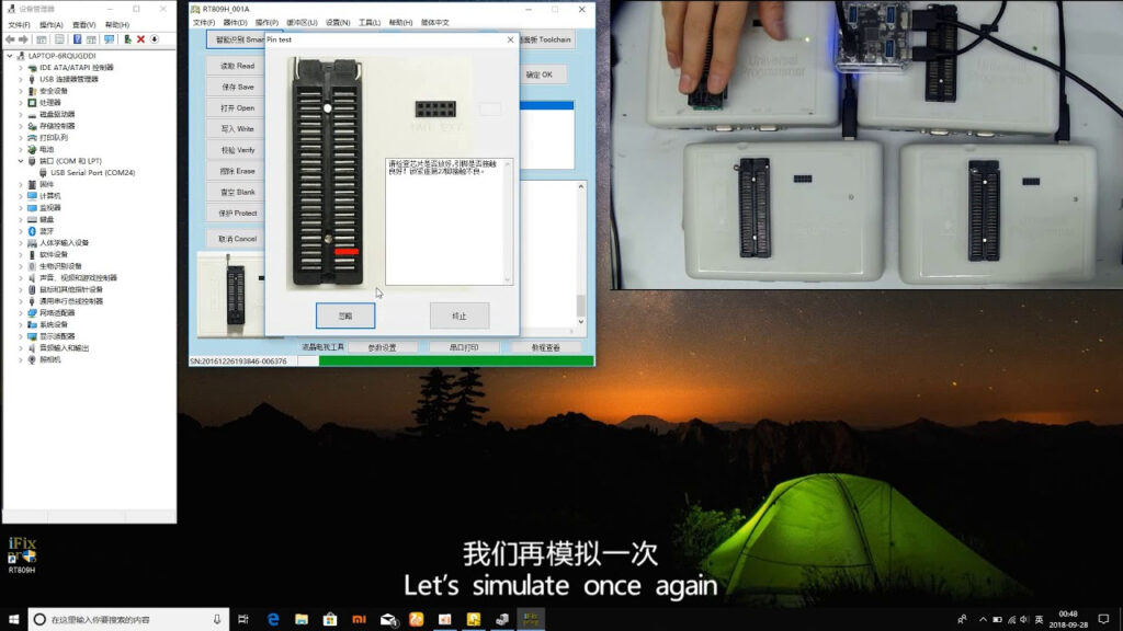
Download the RT809H software from the official website (e.g., RT809.com Manuals) and install it on your Windows PC. Connect the programmer via USB, and ensure the system recognizes it.
Step 2: Identify the Chip
Check the chip’s label to find its model, such as W25Q64FV. This tells you its capacity (e.g., 64Mb) and package type (e.g., SOIC8). Refer to the chip’s datasheet if needed.
Step 3: Select the Right Adapter
Choose an adapter matching your chip’s package. For example:
- SOIC8: Use the SOIC8-DIP8 adapter.
- SOIC16: Use the SOIC16 adapter. Insert the chip into the adapter, aligning pin 1 (usually marked by a dot) with the adapter’s pin 1.
Step 4: Place the Chip in the ZIF Socket
Lift the ZIF socket lever, place the adapter with the chip into the socket, and lower the lever to secure it. Ensure proper alignment to avoid damage.
Step 5: Configure the Software
Open the RT809H software, and select your chip model from the list. If it’s not listed, check the programmer’s compatibility database or update the software.
Step 6: Load the Firmware
Click “Load” and browse to your firmware file (e.g., .bin or .hex format). This is the data you’ll write to the chip.
Step 7: Program the Chip
Hit “Program” to start the process. The software will erase the chip, write the firmware, and verify it automatically. This usually takes a few seconds to minutes, depending on the chip size.
Step 8: Verify the Data
After programming, the software checks if the written data matches the source file. If it passes, remove the chip and test it in your device.
Programming SPI Flash via ISP
In-System Programming (ISP) lets you program the SPI Flash with RT809H without removing it from the circuit board. This is handy for devices where desoldering isn’t practical. Here’s how:
Step 1: Prepare the Connection
Use the ISP cable included with the RT809H. Connect it to the SPI pins on the target board:
- CS: Chip Select
- SCK: Serial Clock
- MISO: Master In Slave Out
- MOSI: Master Out Slave In
- GND: Ground
- VCC: Power (usually 3.3V) Refer to your board’s schematic or chip datasheet for pin locations.
Step 2: Power the Target
Ensure the board is powered, either via the RT809H (if supported) or its own power source. Double-check voltage compatibility (e.g., 3.3V or 5V).
Step 3: Configure the Software
In the RT809H software, select your chip model and switch to ISP mode. Verify the connection settings match your setup.
Step 4: Load the Firmware
Load your firmware file as in the in-socket method.
Step 5: Program via ISP
Click “Program” to write the data directly to the chip. The process mirrors in-socket programming but occurs over the ISP cable.
Step 6: Verify
Confirm the data was written correctly. If successful, your device should now operate with the updated firmware.
Troubleshooting Tips SPI Flash with RT809H
Even with a reliable tool like the SPI Flash with RT809H, issues can arise. Here are common problems and fixes:
- Chip Not Detected: Check chip placement, adapter fit, and USB connection. Update the software if needed.
- Programming Fails: Ensure the chip isn’t write-protected (check the datasheet) and the firmware file is compatible.
- ISP Connection Issues: Verify pin connections and power supply. Loose cables or mismatched voltages are frequent culprits.
Safety Precautions
To protect your chip and programmer:
- Handle chips with care to avoid static discharge—use an anti-static wrist strap if possible.
- Disconnect power when inserting or removing chips from the ZIF socket.
- Confirm the chip model and firmware compatibility to prevent overwriting with incorrect data.
Choosing the Right SPI Flash
Selecting an SPI Flash with RT809H chip depends on your project:
- Capacity: 64Mb (8MB) suits small firmware, while larger chips (e.g., 256Mb) handle bigger data.
- Package: SOIC8 is common for compact designs; WSON or SOIC16 fits higher-capacity chips.
- Application: Firmware storage needs fast read speeds, while data logging may prioritize write endurance.
Check datasheets (e.g., Winbond W25Q64FV) for specifics.
Frequently Asked Questions
What is SPI flash used for?
SPI flash stores firmware, configuration data, or boot code in devices like routers, microcontrollers, and TVs.
Can I program SPI flash without removing it?
Yes, using ISP mode with the RT809H, as long as you can access the SPI pins.
What adapters do I need?
It depends on the chip package—SOIC8 needs a SOIC8-DIP8 adapter, while WSON requires a specific socket.
Adding Value: Practical Tips
To make your programming smoother:
- Backup First: Read and save the chip’s existing data before programming, in case you need to revert.
- Update Software: Use the latest RT809H software for better chip support and performance.
- Test After Programming: Verify the chip works in its intended device to catch errors early.
Conclusion
Programming SPI flash with RT809H is straightforward once you understand the process. Whether you choose in-socket programming for flexibility or ISP for convenience, this guide provides the steps and tips you need to succeed. With its high-speed USB interface, wide chip compatibility, and dual-mode support, the RT809H is a go-to tool for electronics enthusiasts and professionals alike. Try it out, and let us know your experiences or questions in the comments below!